Design Project: Bop-It!
University of Pittsburgh; Department of Electrical and Computer Engineering
ECE 1895: Junior Design Fundamentals
Team: Thomas Driscoll, Meara Murphy, Elizabeth Steward
Design Overview
Our design is a variation of the popular game “Bop It”. Our three distinctly different tactile commands are Squeeze It, Shake It, and Flick It.
· Squeeze It: A stress ball with a conductive pressure sensitive sheet glued inside
· Shake It: Utilizing a tilt sensor
· Flick It: A joystick that accepts movement in any direction
Although our group tested out many different types of audio outputs to indicate which input the game expects the user to enter, we settled on using a buzzer to emit a sequence of notes unique to each input. Our visual cues for the player utilized a RGB LED: red for an incorrect move resulting in a lost game; green for correct inputs; blue for the start and completion of each game played.
Tom was responsible for writing the pseudocode, designing the Upverter schematic and PCB with Lizzie, testing and soldering the PCB board with Meara, and creating the enclosure for our design. This involved taking precise measurements of our final PCB board, designing the enclosure on Fusion 360, 3D printing the design, and fitting the PCB board inside it.
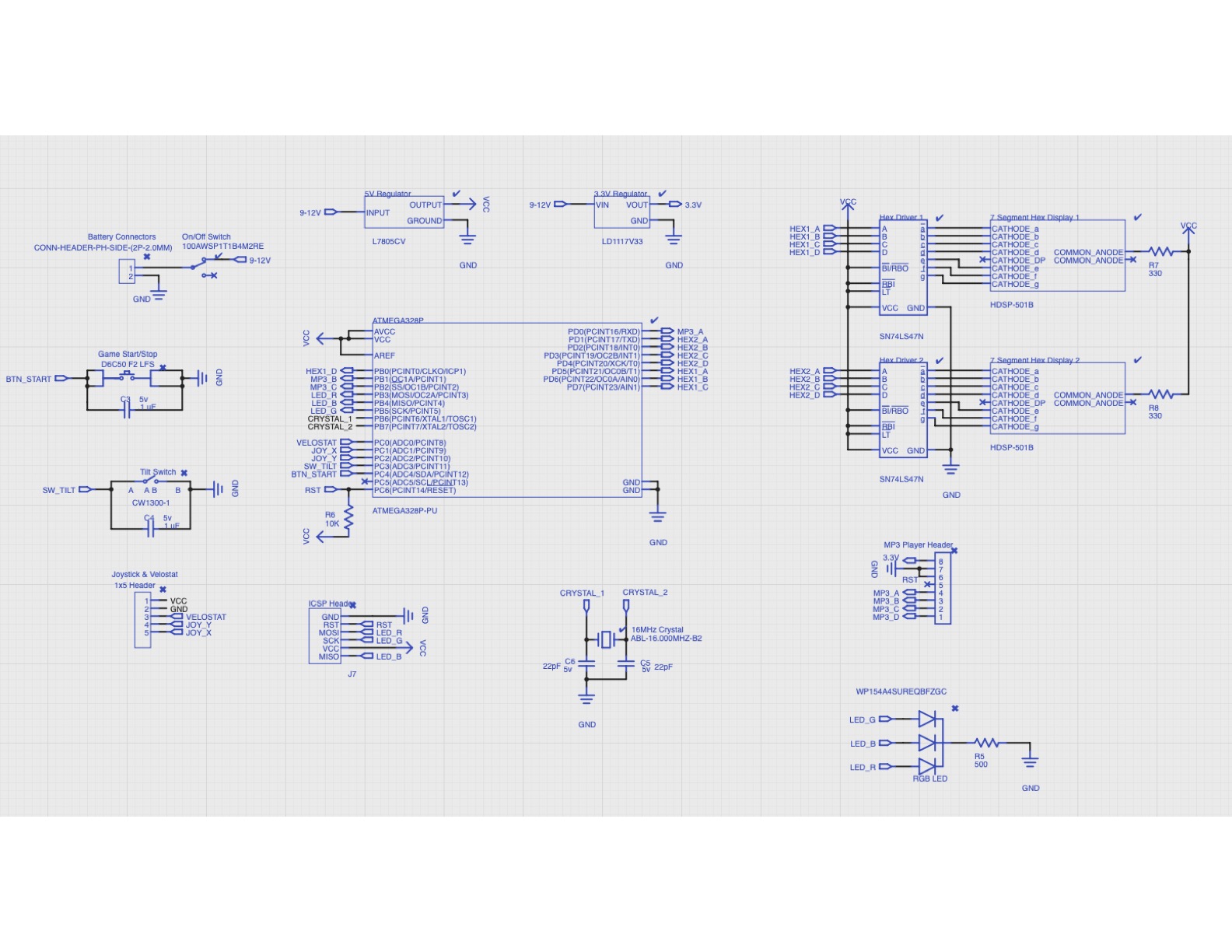
PCB Schematic & Layout
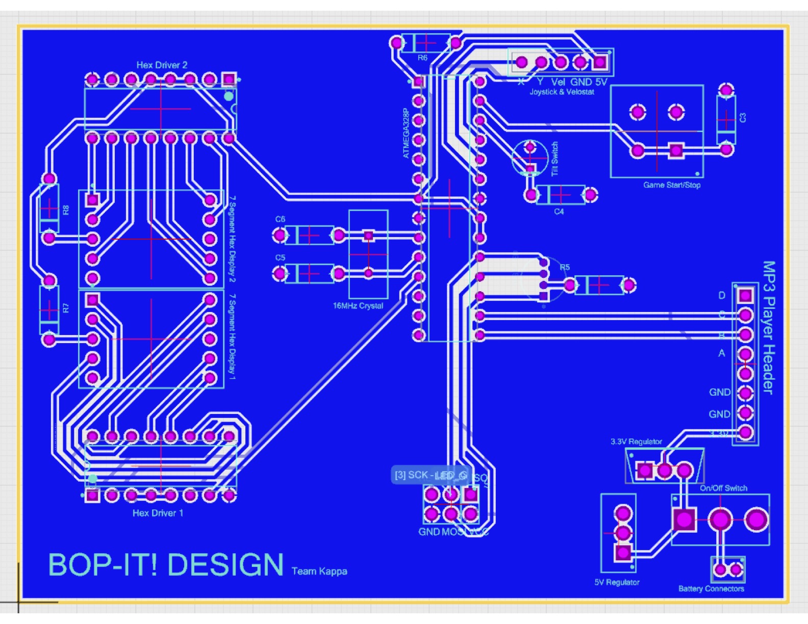
To start, we centered the ATMega328 chip, as this is the focal point of our design. Then, we created all our components and their necessary auxiliary components, such as capacitors, resistors, and ground nets. The schematic was connected using busses. As this was the easiest way to keep track of individual inputs and outputs on the board.
There are a few male header pins in place of components on the board. These were specifically chosen so we could use female-to-female wires to get secure components further away from the PCB, outside of the enclosure, for user interaction. This was especially true for our Squeeze input, as the user is required to squeeze a stress ball with a Velostat pressure-conductive sheet inside.
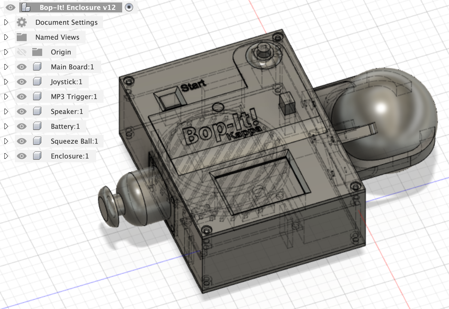
Enclosure Design
The enclosure was the last to be designed after the PCB and parts were chosen. We could have used the PCB layout to determine part spacing and datasheets for other dimensions, but with the slow rolling shipment of parts and the changes we had made, it was better to measure the parts and dimensions after our design was assembled in its entirety.
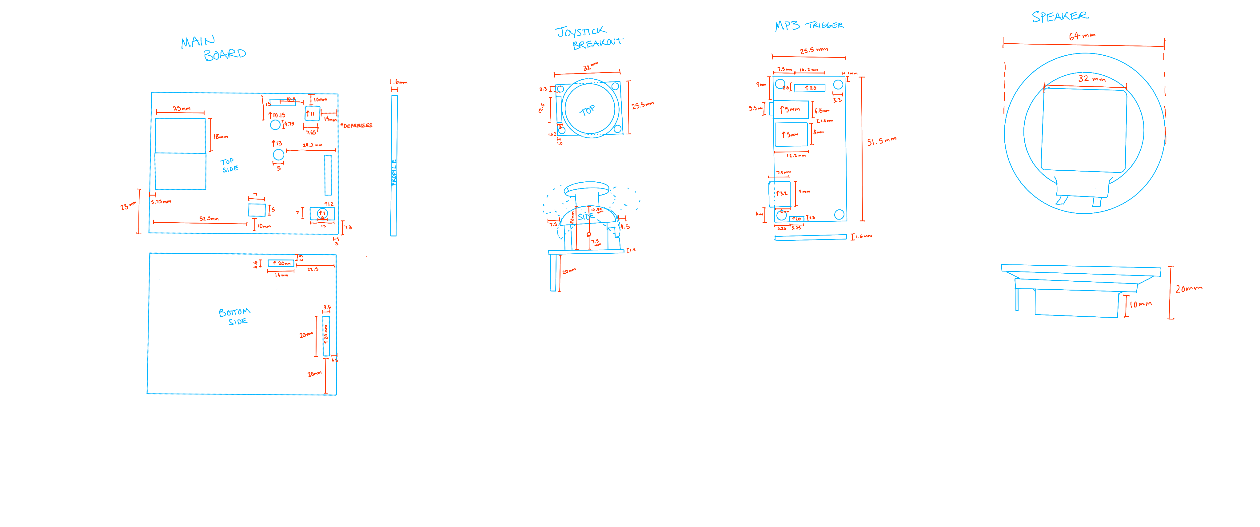
Measurements were made of each of the components protruding significantly from the PCB board that needed clearance, such as the headers and tilt switch, as well as the parts we wanted to expose, like the hex displays and start button. More measurements were taken of the joystick breakout, MP3 trigger board, speaker, and battery. These were all modeled in Fusion 360, which allowed us to rearrange and reconfigure the parts. The most compact arrangement to fit the design placed the joystick on the left, ball on the right, main PCB on the top with the hex displays, button, and toggle switch, and the remaining parts arranged underneath to make one package. The enclosure designed around this arrangement consists of: Top and bottom lid, body, joystick cap, claw, and a center brace.
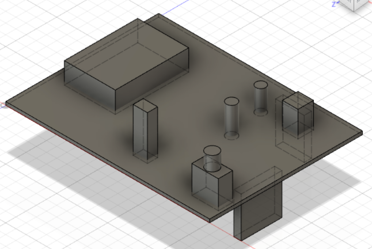
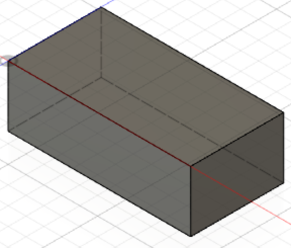
- Top and bottom lids: Due to the tilt switch having a similar height dimension as the start button and hex displays, the top layer was tiered to account for the height differences of the components. The cutout for the hex displays was covered with a thin, clear plastic to act as a protective window. A speaker grill was fitted the bottom lid for unmuffled sound.
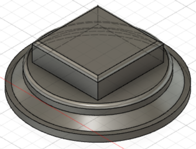
- Joystick: Was devised with mounting holes to match the mounting holes on the joystick breakout board, as well as clearance to move the joystick in each direction. This cap is mounted to a matching cutout on the body with super glue.
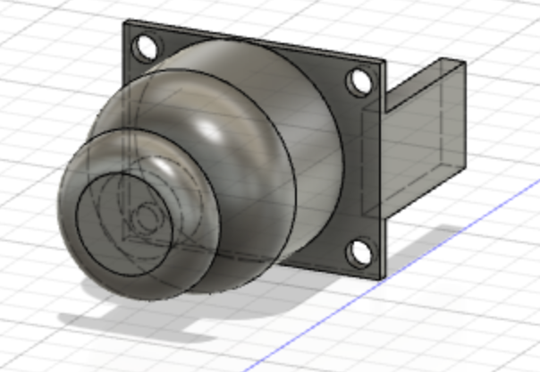
- Claw for the squeeze ball: Designed to allow the ball to be secured, while also allowing space for it to compress. It has two main arms with corners protruding out to be glued and secured into matching cutouts in the ball. These main arms secured the ball, with four smaller arms to ensure the ball remains in place while squeezing. One main arm contains a cutout for the hidden sensor wires that are glued into the ball. Once printed, there was not enough room for the ball to flatten outwards while being squeezed, requiring the removal of one of the main arms, as seen in the final design. This claw was secured to the enclosure body with four 3mm screws.
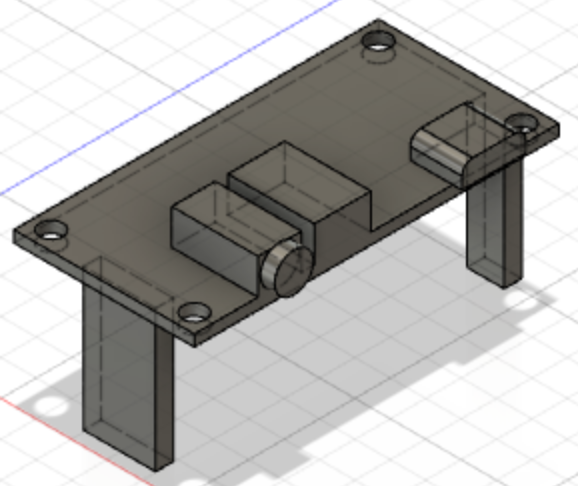
- Center brace: Fabricated to hold the speaker, MP3 Trigger, while leaving enough space for the battery. It also acts as the securement for the main PCB into the enclosure using a pressure-fit.
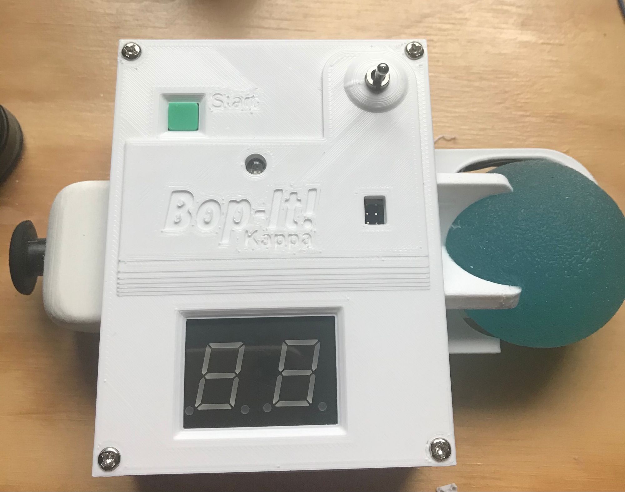
The enclosure design was manufactured in individual parts on a 3D printer over the course of two days. The various parts were screwed, glued, and fitted in as intended, with the only modification being the removal of one arm of the claw. The components and PCBs were then assembled and installed, completing the design.