Design Project: Useless Machine
University of Pittsburgh; Department of Electrical and Computer Engineering
ECE 1895: Junior Design Fundamentals
Individual Assignment
The goal of this design project was to practice designing, modifying, creating, and
testing a PCB design as part of the Junior Design course at the University of Pittsburgh. The design was to be previously designed and created a part of another project, using it as a reference to create a modified version with simple changes as a schematic. We submitted this as a design proposal. We then follow up with simulation and validation of the design, collect and submit a bill of materials, leading to sketching a PCB layout that would be later manufactured. We then implement and realize the design using soldering skills, test its functionality, followed by a final reflection of the entire process in a lab
write-up detailing the process.
Design Overview
The project I referenced was of a “Useless Machine” that was designed in a way that when switched on, uses a level to mechanically switch the machine back off, returning back to its original state. Most designs like these use either a microcontroller or direct-drive of a motor, however those designs when “off” are still consuming power at some level. This implementation uses a 555 timer that allows it to avoid the idle power consumption, and therefore truly reaches a powered-off state. Changes to the original source design: male header pins were added leading out from the PCB for easy removable and rearrangement during assembly.
The 555 timer is used as an astable oscillator, with a DPDT toggle switch changing the value of the resistor attached to the chip. The driving pulses of servos are between 1 to 2 ms, using the oscillating frequency of the timer to drive a servo to two positions. The closer to a 1 ms time high pulse, the closer to an angle of 0 degrees. The closer to 2 ms time high pulse, the closer to an angle of 180 degrees. When put in the “ON” position the servo’s mechanical lever rotates, with the end of the lever eventually greeting the DPST switch and toggling it back into the “OFF” state. This changes the timer's resistor value back, now oscillating with a frequency that sends the servo lever back down.
In order to achieve a truly powered-off status, the design first makes use of the DPDT toggle switch’s second set of connections. When the DPDT is switched on, the VCC line containing +5v is connected to the rest of the timer circuit, powering it. When the servo rotates up to its ending “ON” position and hits the DPDT switch back off, it cuts power to the timer.
In order to power the timer to have the servo retract, we use a SPDT Micro-switch placed at the base of the servo lever arm and wire it to connect the VCC line to the circuit when in an un-pressed state. That way, when the DPDT switch is toggled on, powering the circuit initially, and the servo starts rotating to “ON”, the SPDT Micro-switch becomes un-pressed, also powering the circuit. During that time, the 555 timer astable circuit has connections to +5v via the DPDT switch in addition to the SPDT Micro-switch at the base of the servo. When the DPDT is toggled back to “OFF” via the servo lever arm, the DPDT’s VCC line becomes disconnected, but the 555 timer circuit is still powered from the SPDT Micro-switch VCC connection, allowing the second oscillating frequency to drive the servo back into the enclosure. When the servo retracts entirely into the box and rotates all the way down, the lever arm pressed the SPDT Micro-switch and un-powering the entire circuit. Disconnected from the DPDT and the SPDT Micro-switch, the device is then in a completely unpowered state.
Design Verification
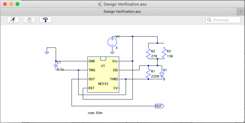
A mockup of the circuit was designed in LTSpice to model the waveforms produced by the 555 timer, and make sure the timings would properly drive the servo.
The implementation was built using an NE555 timer chip, and generic components the resistor, capacitor, and diode. To represent the two operating states controlled by a mechanical switch, two different waveforms were simulated: one with the R2 resistor connected, and one with the R3 resistor connected. The simulations were all transient analysis lasting 30 ms each.
The oscillating pulses in the simulation were not close to the calculated values. To verify that there was a problem with the design I attempted to breadboard the circuit, where it also did not behave as expected. While changing angles were achieved, the servo was jittery when doing so. This was probably due to temporarily using a burnt LED in place of the D1 diode; I revisited this later.
Design Implementation
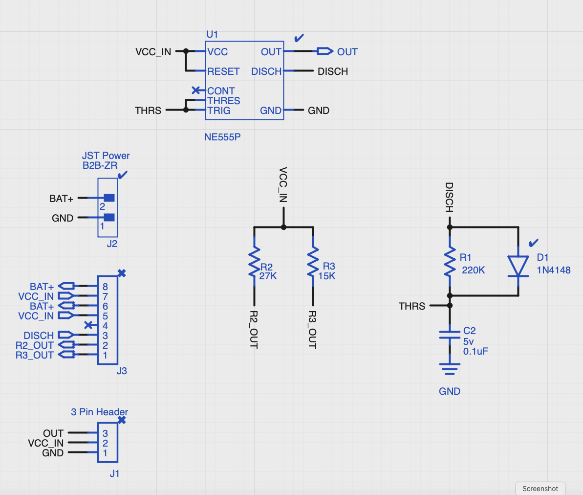
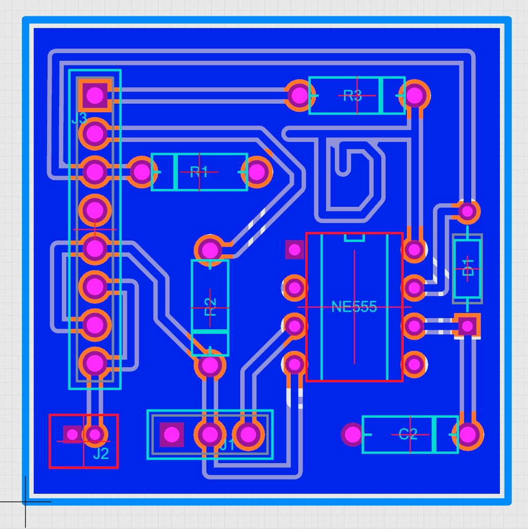
The design was created in Upverter (above), an online PCB tool from the makers of Altium Designer, a current industry leader and standard for a PCB design tool. One the bottom left are the sets of male header pins. The set of three (labeled J1) is for the servo, with VCC, GND, and OUT. The set of 8 pins (labeled J2) are used for the connections to the DPDT switch and the SPDT Micro-switch. Above those two is the JST connector (labeled J2) for power. These headers and JST connector allow the exclusion of the switches and power supply to be left off of the board, shrinking the PCB design significantly because they are unnecessary to have mounted to the PCB directly. The 555 timer is represented by the generic NE555P package, and the resistors, capacitors, and diodes are generic axial through-hole components. This was rearranged into the PCB board layout (below).
The components in the bill of materials were the ones recommended in the original project, other than the JST connector and header pins. Most important was getting a proper servo with the right PWM signaling and torque, hence using the recommended one.
Design Assembly
The 8-chip 555 timer package and through-hole components were soldered on the PCB, and flush wire snips were used to remove the excess component leads. The male header pins were placed next, tack soldering each end with the PCB on its side before moving to the back.
When it came time for the JST connector, it was realized the size of the JST connector holes on the PCB were too small to match the ordered component. As a work-around, the design was modified to have lead-wires running off of the board from where the JST connector would have been to a DC Barrel Jack. This works as a replacement for being able to connect and disconnect the power source.
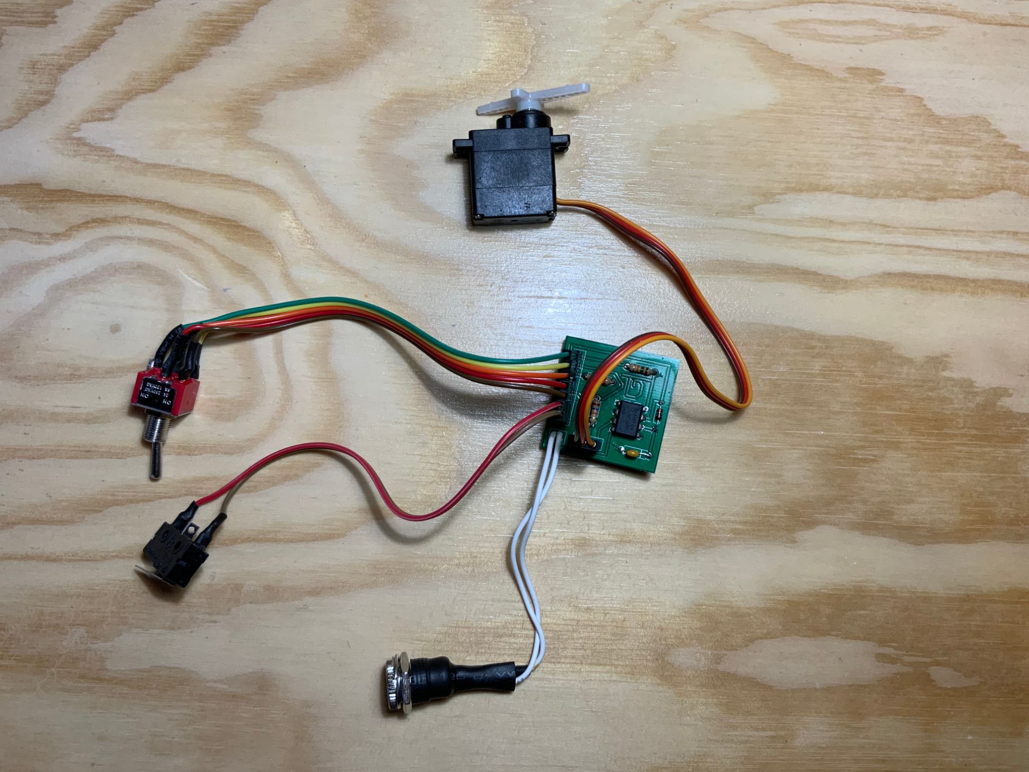
The DPDT and SPDT Micro-switch were give wires with female pin connectors, and the soldered joints given heat-shrink tubing to protect the connections. Putting all of the pieces together, the switches and the servo were connected to the male header pins on the board, and 4AA batteries were put into the battery holder and connected to the DC barrel jack.
Design Testing
Once all connected, the servo whirred to life. This was a good start because it means there is oscillation coming from the 555 timer, as well as the SPDT Micro-switch was unpressed at that moment, putting the circuit into a powered state like it was. Pressing the switch, the servo stopped humming in its current position, another good sign that the circuit was working and wired correctly because it meant the power was cut off.
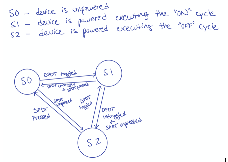
The testing done was based on the state machine slayed out as follows, creating six test situations:
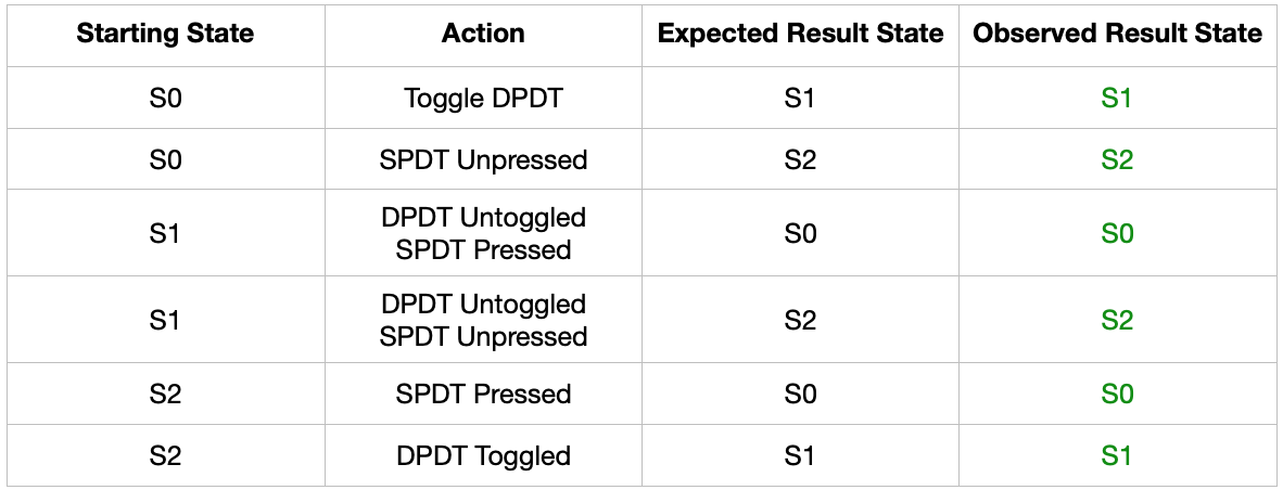
With all of the different combinations and transitions executing as expected, the next testing done was for the mechanical design with the servo lever arm. This was prototyped out of cardboard for ease, convenience, and rapid design iterating of position, size, shape, and placement of components.
A vertical wall was picked as the best way to temporarily display the workings of the mechanism and visualization of the interaction of components with each other. A slate was cut out of a cardboard sheet with two supports interlocked.
A challenge was to determine the arrangement of the toggle switch and the servo. What had to be taken into account was making sure the toggle switch toggle “ON” going opposite the direction of rotation of the servo arm. This is so that the design works mechanically, in that after switching the toggle “ON” the servo will rotate the arm in the direction of the toggle switch, making contact with it, and continuing in that direction to push the DPDT into the “OFF” position.
The servo arm shape and the SPDT Micro-switch placement have to work mechanically together too. The arm was designed so that in the “OFF” position it has a flat bottom edge to make clear contact with the horizontal trigger of the Micro-switch. The rest of the components were arranged and attached to the wall purely for convenience and portability.
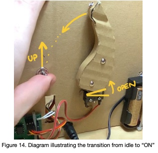
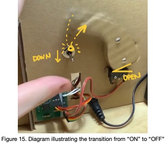
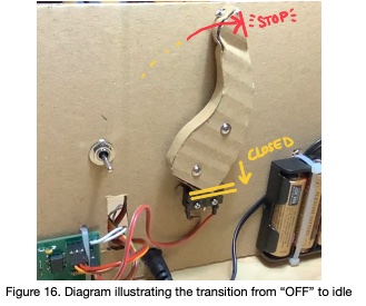
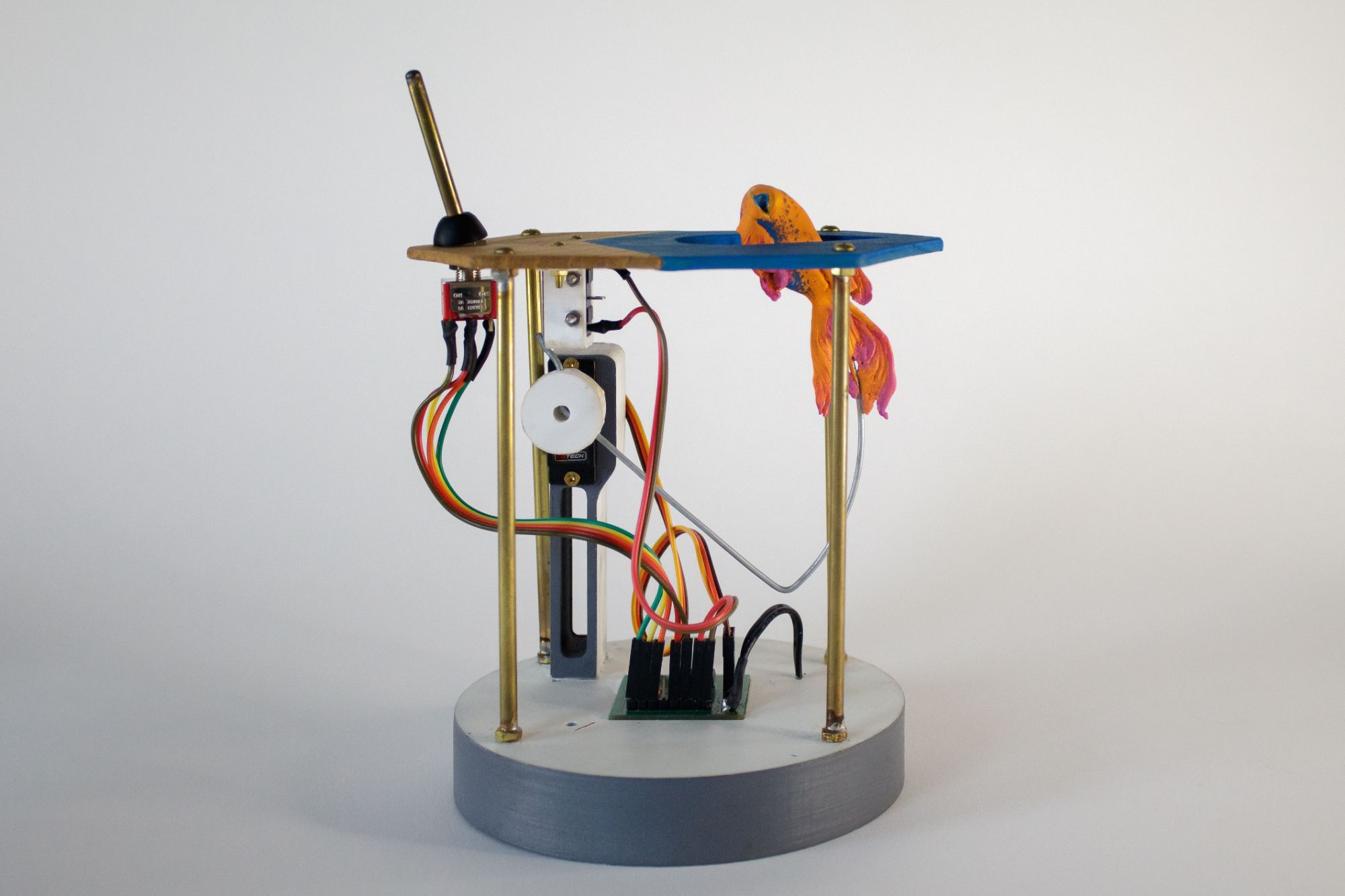
The completed prototype (Figure 14) was then given a full run-through test. The DPDT toggle switch was thrown upwards into the “ON” position. This powered the circuit and sends the servo rotating left and down, simultaneously unpressing the SPDT Micro-switch. (Figure 15). Once the servo’s lever arm makes contact with the DPDT toggle switch, it pushes it into the “OFF” position. Still powered by the unpressed Micro-switch the servo is sent rotation right and up back into its original position where it eventually depressed the trigger of the Micro-switch, unpowered the circuit, and leaving the device in a powerless, idle state (Figure 16).
Conclusions
This project, and course so far, has been a great learning experience into practical PCB work and guidelines. Being my first PCB ever designed and manufactured, this design is satisfactory for what was accomplished through recreating a project schematic found online. Improvements can be made in the simulation and design verification, but the design was still successful in a practical manner. I would also consider not use pin headers for connecting the switches to the circuit; it was more difficult trying to determine which wire from the switch matched which pin on the board than it would have been to solder them directly, however for prototyping and debugging a design having the removable, and even technically rearrangeable, is worth it. Finally, I would confirm the sizes of components to order on the bill of materials with the generic components used on the PCB layout.